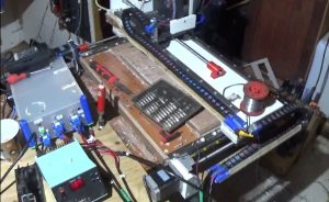
I continued the work with the milling machine to build a control box for the electronics. I made the box from 6 mm plywood in addition to the side on which all socket contacts were to be mounted and the lid, I made them from 5 mm acrylic plastic. I made the base plate from 1.5 mm aluminum plate. The corners for the box I printed on my 3D printer in blue PLA. I also took the opportunity to print links in black PLA to the cable chains when the printer was still there.
When the cable chains and electronics box were assembled, a lot of test milling followed. Unfortunately, it turned out that the Z-axis, which consisted of the Biltema cutter, and the X-axis, which only consisted of a simple plywood slide not meet my expectations. The precision was all too poor and a rebuild of Z and X had to be done.
Before I disassembled the cutter to start the rebuild, I milled out the Corian details I needed to build a new Z-axis and a new motor mounts for new stronger stepper motors of type Nema 23 for all axles. For this purpose, the accuracy was sufficient, so it was not completely useless after all. The Corian part to the upper part of the X-axis was too big so I made it manually.
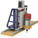
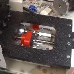
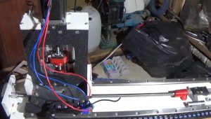
In order not to have to change too much on the existing machine, I decided to just put a Corian lid over the plywood slide that the milling motor previously ran in. I then mounted two linear rails for the X-axis, that came from a used production machine. They were of an adjustable type and basically like new so they fit well. I also replaced the usual M10x1.5 mm standard threaded rods in all 3 axles with real ball screws 12×4 mm. The Z-screw gave a movement of 45 mm which is Ok. Unfortunately, both the X and Y axes are a bit too short, which limits the work surface somewhat, but I can live with that until further notice. Purchases of longer screws will take place when the economy allows.
The Z-shaft I built from 12.3 mm Corian which I milled out with the old cutter before I disassembled it. The linear bearings are 12 mm round bar with ball bushings. Holders for the round bar, axial bearings, ball nut holders and holders for the milling motor are printed in PLA.
After mounting Z and X, the final assembly of limit switches, etc. followed. I mounted switches at both ends of all three axles to eliminate the risk of collision. On the previous version, I only had switches in the home positions, which meant that I broke 2 clutches and the holders for the thrust bearings on the Y-axis when I drove too far by mistake.

Leave a Reply